
The art of archaeological planning


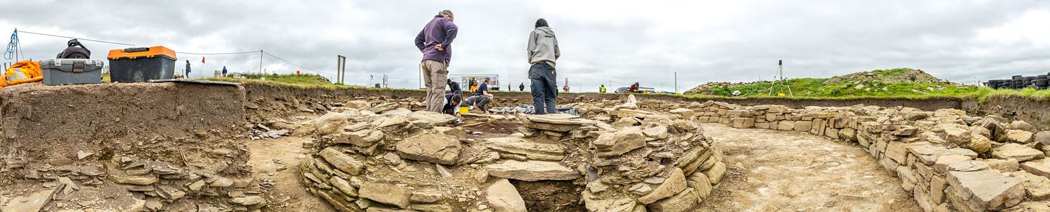
Visit the Ness site at any time during an excavation season and you are guaranteed to see at least one person hunched over a wooden frame with pencil, drawing board and plumb line in hand.
What these people are doing is drawing plans — a vital part of any archaeological dig and part of the site archive where we endeavour to record everything on site using every method at our disposal.
Many experienced diggers enjoy planning.
Others, and especially those with bad backs, find it something of a trial as they have to lean over planning areas at uncomfortable angles.
But a well-executed plan records details that you just can’t get with photography alone.

Photography and line drawings do complement each other but photogrammetry is also used and at times can replace traditional drawn plans.
Site plans are generally drawn at a scale of 1:20 as this caters well for structural detail.
Large open area sites with few structural features can be drawn at 1:50 while a scale of 1:10 or 1:5 may be required for section drawings, detailed contexts or features (e.g. artefact spreads or human skeletal remains).

It will come as no surprise that drawing an accurate plan is a time-consuming process.
To transfer what the planner sees on to paper relies on planning frames — metre-square “boxes” that have been divided into a grid with string.
Before the first pencil mark, these frames must be carefully set up and aligned to the site grid to ensure accuracy and consistency across the excavation.
That done, the planning can begin.
In simplest terms — and I may be showing my age here — the art of planning is very similar to those “gridded-enlargement” games (see below) that graced the activity books of my childhood.

With these, one gridded box contained a picture that you copied into the larger, empty box by matching the position of the lines in relation to both grids.
Planning is much the same.
The wooden frame is the source and the size and position of various elements viewed within it are transferred, with the aid of a tape measure and plumb line, on to the planning sheet.

The key rules of drawing an archaeological plan are:
- Draw only what appears in the frame.
- Draw each square in the frame systematically, making sure nothing is left out.
- Stand vertically over the frame to avoid parallax (the distortion caused by viewing, and drawing, an object at an angle rather from directly above) and use a plumb line to check the position of context boundaries and the edges of stones.
- Check and sort out any anomalies as they occur (e.g. the plan doesn’t seem to fit from frame to frame). Cumulative small errors due to setting up and parallax can cause large discrepancies over an area.
- Check adjacent plans to ensure that all squares are being covered and that plans appear to join up.
- And finally take the time to look at your drawn image and make sure that it bears a close resemblance to what is on the ground!
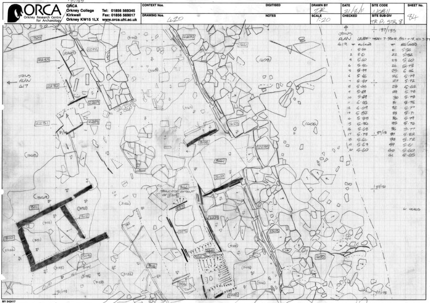
Covering all these points means that a finished plan is often a marvellous sight to behold, incorporating:
- Stones, structural or otherwise, over 5cm in size.
- Context boundaries.
- Changes in soil colour or texture.
- Cut feature edges e.g. pits, post holes, ditches etc.
- Slopes. These may not follow context boundaries and can vary inside a cut feature.
- Structures and orthostats.
- In-situ artefacts.
- Tool marks, even artwork or geological features.

Done correctly, a completed plan will line up perfectly with others in the vicinity as well as provide a record of the excavated area over time.
By overlaying plans from different phases of excavation it is possible to see earlier and later features of a trench in relation to one another other.


